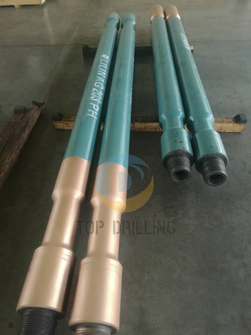
Friction reduction tool
1. Structure
The friction reduction tool system relies on three main parts:
©~Shocking tool
﹡Power section
﹡Disc valve and bearing system
2 .Principle
The friction reduction tool itself to produce longitudinal vibration to improve weight transfer in the drilling process efectiveness and reduce the friction between the drill and hole at the bottom, this means that drilling with tool can be used in a variety of modes, particularly in power drilling directional drilling is used to improve weight transfer, reducing the likelihood of BHA sticking to reduce torsional vibration and borehole wall friction, reduce stick-slip vibration in the drilling process, increase the penetration rate and extended bit life, and possibly guided and motor coordination, to improve control of the tool.
Technical specifications
Tool size
(in) | Flow rate
(L/S) | Pressure
(Mpa) | Operating frequency
(Hz) | Temp range
(℃) | Max.pull
(kN) | Max.torque
(kN.m) | Overall length
(mm) | Conn. |
8 | 32-55 | 3.5-4.2 | 13-17 | ≤150 | 3220 | 18 | 7100±5 | 6 5/8REG |
6-3/4 | 25-37.8 | 3.5-4.2 | 13-19 | ≤150 | 2535 | 15 | 7230±5 | 4 1/2IF |
6-3/4
low pressure | 25-37.8 | 2.5-3.5 | 13-19 | ≤150 | 2535 | 15 | 7230±5 | 4 1/2IF |
4-3/4 | 9.5-17 | 3.5-4.2 | 11-20 | ≤150 | 1156 | 12 | 4965±5 | 3 1/2IF |
4-3/4
low pressure | 9.5-17 | 2.5-3.5 | 11-20 | ≤150 | 1156 | 12 | 4965±5 | 3 1/2IF |
 sales@top-drilling.com


 Current location: